


Introduction
Computed tomography (CT) is an excellent tool allowing for guidance of percutaneous interventions, such as the biopsies or drainages that often take the place of more invasive surgical procedures. However, one of its limitations is exposure to radiation, for both patients and operators [1].
The application of new-generation CT scanners and development of CT-guidance techniques have led to a substantial reduction in radiation doses received by operators. Among the 3 ways of performing CT-guided interventions, one involves the scanner room being left for the time of the exposure (scan – change needle position – leave the room and scan – change needle position, etc.). However, this increases the duration of the procedure and is less convenient for the operator. In contrast, the 2 other methods require a radiologist to remain in the scanning room while the exposures are taking place. CT fluoro-scopy is activated by a radiologist stepping on a pedal and keeping their foot on it, and in this way presenting images updated constantly and viewed in real time. Finally, the quick-check (intermittent) method allows for the acqui-sition of 3 contiguous images with a single pedal step, i.e. the target slice, a slice taken cranially, and one taken caudally. Thanks to this technique, an operator avoids continuous exposure to radiation [2].
Shielding equipment such as lead aprons, radiation attenuation gloves, glasses, and drapes placed over the patient’s body have gained common use with a view to increasing staff safety. Nevertheless, because the dose decreases with the square of the distance from the beam, it would seem crucial for distance from the gantry and patient in the course of exposures to be maintained [3]. Equally, a walk of even a few steps away from the scanner is often impossible, especially when a procedure requires rapid changes of needle position, e.g. in lung biopsy. A procedure will also be prolonged in this way.
While the lead X-ray screens that are common in conventional radiology units may also be used to protect staff in the course of CT-guided procedures [4], to the best of our knowledge, they have not gained wide application, and have not yet been evaluated for their effectiveness.
The aim of the work presented here was to evaluate the efficacy of a lead screen in reducing the radiation dose received by an operator during CT-guided interventions. This was done by measuring radiation at different locations in the room while procedures were performed with a mobile X-ray lead screen in use.
Material and methods
Approval for the prospective study was obtained from the Institutional Review Board, prior to the evaluation of data from 72 consecutive CT-guided interventions performed between October 2018 and January 2019. The procedures included biopsies (55), drainages (12), intrathecal administrations of medication (4), and celiac plexus neurolysis (1). These types of procedure included within the study were chosen in line with their similarity of duration (less than 1 hour in each case, including preparation). Procedures typically taking more than an hour (such as ablations) were excluded from the study in this context.
All procedures were performed by one of three board-certified radiologists with at least 6 years’ experience in CT-guided procedures. The interventions were carried out on a 320-row CT scanner (Aquilion One, Toshiba/Canon Medical Systems), with a tube voltage of 120 kV and tube current of 50 mA. In all (N = 18) lung biopsies a tube current of 10 mA was used, to reduce radiation while still ensuring the acquisition of good-quality images. This is a standard procedure at the department. All procedures were performed using the quick-check method, with no CT fluoroscopy applied. During all interventions, a mobile X-ray screen with 0.5 mm Pb equivalent containing a window (2.2 mm Pb equivalent) was placed between the operator and the CT-scanner (Figures 1, 2, and 3).
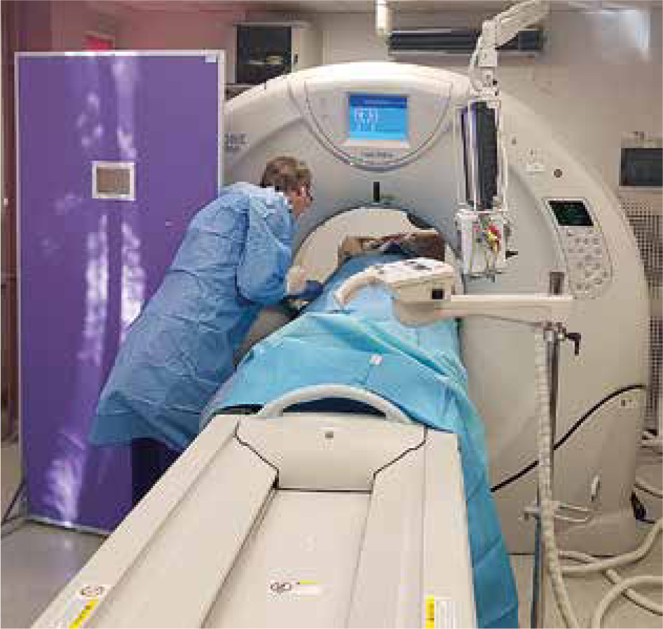
Figure 2
A quick-check computed tomography scan – a radiologist operating the pedal while remaining behind the lead screen
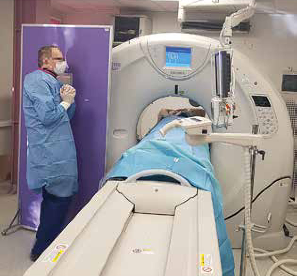
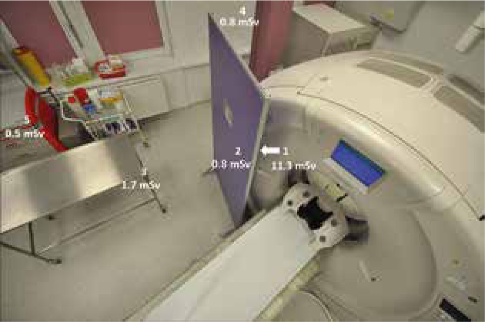
Figure 3
The placement of the 5 dosimeters around the computed tomography scanner (as seen from above)
All procedures were performed under local anaesthesia. The procedure protocol in our Institution consists of a helical scan of 100-160 mm covering the region of interest and allowing for localization of the given lesion and planning of the relevant procedure. It is followed by a 3-slice series (of 4 mm – 8 mm – 4 mm slice thicknesses) using intermittent exposures to complete the procedure, with one wider scan to allow for the detection of early complications such as bleeding or adjacent organ injury. In our study, for the duration of the intermittent exposures, the operator stepped behind the screen in the manner shown in Figures 1 and 2. The radiologists all wore standard lead aprons and thyroid collars.
Optically stimulated luminescence dosimeters (OSL, beryllium oxide, BeO) were used, with 5 of these placed around the CT scanning room: 2 on each side of the lead X-ray screen placed between the operator and the CT scanner. These 2 dosimeters simulated radiation exposure with and without the X-ray protection screen. The other 3 dosimeters were placed at the side of the gantry, obliquely on the instrument trolley, and obliquely at a greater distance from the gantry. A detailed depiction of the distribution of dosimeters is as provided in Figure 3. The radiation doses accumulated at each dosimeter were measured. Univariate analysis of variance (ANOVA) was applied to check for differences in the mean radiation doses in each dosimeter. Then Tukey’s post-hoc test was applied to estimate the significance of differences.
Results
Table 1 presents the cumulative doses measured by each dosimeter. The highest level of radiation exposure (11.33 ± 1.93 mSv) was noted at the dosimeter placed on the gantry side of the X-ray screen (dosimeter 1). The 4 other dosimeters placed on the operator side of the screen or at a greater distance from the gantry noted much lower levels of exposure, ranging from 0.53 (± 0.09) mSv to 1.67 (± 0.28) mSv.
Table 1
Doses measured by each dosimeter placed in the computed tomography room
The results of one-way analysis of variance (ANOVA) emerged as significant – F(4, 355) = 2026.75, p < 0.001, η2 = 0.96, indicating differences in the mean radiation doses recorded by each dosimeter. In the next step, Tukey’s post-hoc tests showed the following differences: a) the dosimeter located in position No. 1 recorded a dose significantly higher than all other devices (at p < 0.001); b) the dosimeter at location No. 3 registered a significantly higher dose than those in positions 2, 4, and 5 (p < 0.001). Dosimeters Nos. 2, 4, and 5 did not differ in terms of their readings for the average dose of radiation.
The presence of the screen caused no discomfort for the operators, while access to the patient and needles proved sufficient during all procedures (Figures 1 and 2).
Discussion
CT is a popular guidance tool that allows biopsies, drainages, and other percutaneous interventions to be performed with high efficacy and safety. In the most popular setting, the interventional radiologist remains in the scanning room while exposure is ongoing. Various measures can be taken to keep a radiologist’s radiation exposure as low as reasonably possible, and it is accepted that a lead drape placed on the patient reduces levels of scattered radiation [5].
While all radiologists wear X-ray protective aprons and collars, it would seem possible for more to be done towards radiation protection in the course of CT-guided interventions. The SIR Best Practices for CT-guided Interventional Procedures [4] acknowledge the possibility of a mobile lead barrier being used where people remain stationary during a procedure, as is the case for an anaesthesiology team. A mobile lead barrier is mentioned there as an alternative to protective clothing rather than a supplementation. Lead screens are not used frequently in interventional CT-suites, and to the best of our knowledge no studies on their use in such a setting have been published.
By measuring cumulative doses at different locations in the gantry room during a series of interventions, we attempted to find the optimal location for the operator in terms of radiation exposure. Our study shows that, by using an X-ray lead screen placed between the CT scanner and the operator, we achieved radiation exposure at the procedure site similar to that present at a greater distance from the gantry, i.e. the side of the scanner. It was also only around 7% as high as on the scanner side of the lead screen, which would correspond to the setting without a protective screen (dosimeter 1). This is very useful information implying that the need to move away from the gantry at times of exposure may be eliminated by the use of a lead screen, with time and effort saved as a result. The radiation dose at 3 m away from the gantry (dosimeter 5) was even lower, but moving such a long distance away from the patient takes more time and requires walking around the back table. This could be problematic, especially in procedures that require quick changes of needle position, e.g. lung biopsy.
Numerous studies have shown that, although the radiation dose to a radiologist during CT-guided procedures is low, substantial exposure may be received by the radio-logist’s hand because the biopsy needle is held during scanning [6]. To overcome that necessity, some authors recommend the use of needle-stabilizing techniques such as Steri-Strips [7] or needle-holders [8]. At our institution, radiologists avoid holding the needle and use wet gauze cloths if it is necessary to rest it. However, no bone biopsies requiring heavier needles and a more complex holding method are performed.
Application of lower (fixed) tube current or voltage is another efficient way to reduce radiation exposure to the patient and the operator [9-11]. Neeman et al. reported an 85-95% reduction in radiation dose using tungsten antimony shielding [12], but installing this proves time-consuming and its usage looks cumbersome.
Apart from promoting technical advance and equipment modifications, awareness of dose distribution in the study room can help in the development of a safe workflow for interventional radiologists. It should be noted that levels of radiation are highest along a line perpendicular to the gantry, while reducing towards the gantry side because the gantry itself offers shielding against radiation. This means that stepping away from the gantry during exposures – to a safer location like the gantry side – is one of the self-protection methods applied by staff [3, 13]. Operating from the head of the patient has also been found to favour staff safety but has not gained more widespread adoption for practical reasons [13]. In this study we showed that, in terms of exposure to radiation, the placing of an X-ray screen between the scanner and the radiologist may yield a similar outcome to stepping away from the scanner, while presumably being more practical and time-saving. The proposed solution was neither uncomfortable nor disturbing for the operator.
This study has several limitations. First, the dose accumulated by dosimeters is measured, rather than those acquired separately in the course of each individual procedure. Furthermore, our study results do not reflect staff exposure directly because dosimeters placed in the room do not fully reproduce the circumstances in which an operating radiologist also wears lead-lined protective clothing. Greater reliability would indeed have been achieved had we compared radiation exposure under an apron in the course of CT-guided procedures, with and without the X-ray screen under test. However, previous publications report a correlation between the dose length product and the operator’s dose [14]. Also, X-ray protection screens for CT-guided procedures have been in use at our institution for many years, and it does not seem ethical to remove them solely for research purposes.